This section provides guidance on Erosion and Sediment Control, Section 4 in the Construction BMP Handbook.
A PDF of this entire section can be downloaded here.
Click on the topics below to navigate to each section.
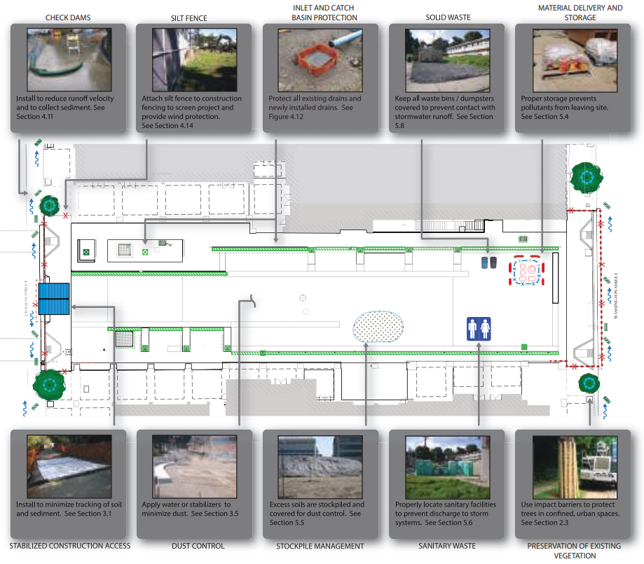
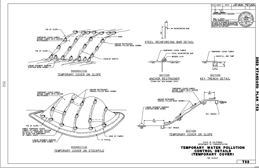
plan overview: Click For full sized image
DESCRIPTION
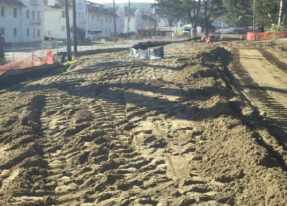
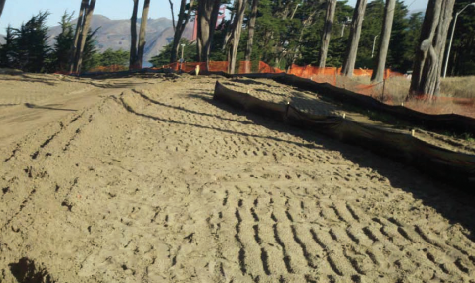
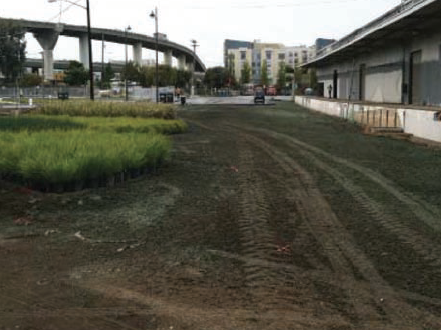
Soil preparation and roughening involves the assessment and preparation of surface soils for BMP installation. This preparation should include soil testing and recommendations for correcting compacted soils. Roughening surface soils by mechanical methods maybe required to prepare soil for additional BMPs or break up overland flow. Soil preparation can also involve tilling topsoil to prepare a seed bed and incorporating soil amendments to enhance vegetative establishment.
APPLICABILITY
GUIDELINES
MAINTENANCE AND INSPECTION
Check the seeded slopes for signs of erosion such as rills and gullies. Fill these areas slightly above the original grade, then reseed and mulch as soon as possible.
examples of soil roughening

GUIDELINES
When choosing a product appropriate for the specific site condition consider:
- Effectiveness of reducing erosion, flow velocity, and runoff
- Compatibility with native plants, wildlife, moisture retention
- Durability, longevity, and projected maintenance
- Plastic products are not allowed in areas that protect wildlife such as the San Francisco Garter Snake and the California Red-legged Frog
DESCRIPTION
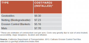
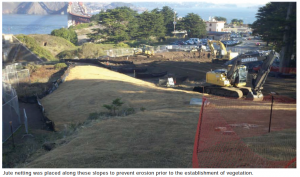
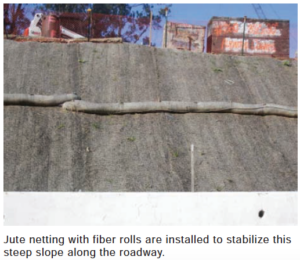
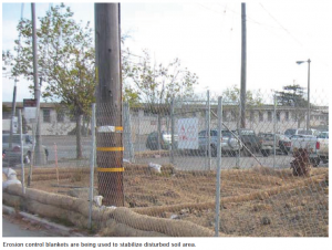
Rolled erosion control products (RECPs) are used in combination with topsoiling, soil amendments and vegetative growth to form surfaces that help to protect disturbed soil areas from the erosive forces of water, wind or the scouring forces of channelized flow. RECPs involve the placement of geotextiles, plastic covers, and erosion control blankets and mats to stabilize disturbed soil areas, and protect soil from erosion by wind or water. RECPs can be used as stand-alone soil stabilization BMPs or in conjunction with re-vegetation. They can also be used to reinforce mulch.
TYPES OF RECPs
INSTALLATION
Remove all rocks, clods, vegetation, or other obstructions and grade to allow the blanket/mat to come into consistent contact with the soil surface. Improper installation allows rain runoff to flow under the blanket.
Ensure RECPs are adequately overlapped and securely anchored to resist the effects of wind and water.
If the area is to be mowed at a later date, the anchoring staples or stake pins should be driven flush to the soil surface to avoid a potential hazard during mowing.
Install in accordance with manufacturer’s instructions.
Cost estimate per acre
examples of jute netting
MAINTENANCE AND INSPECTION
RECPs should be inspected periodically and after rainstorms for signs of erosion or undermining. Failures should be corrected immediately. Material should be reinstalled following any tears or separations, and the slope or channel should be backfilled and stabilized.
DESCRIPTION
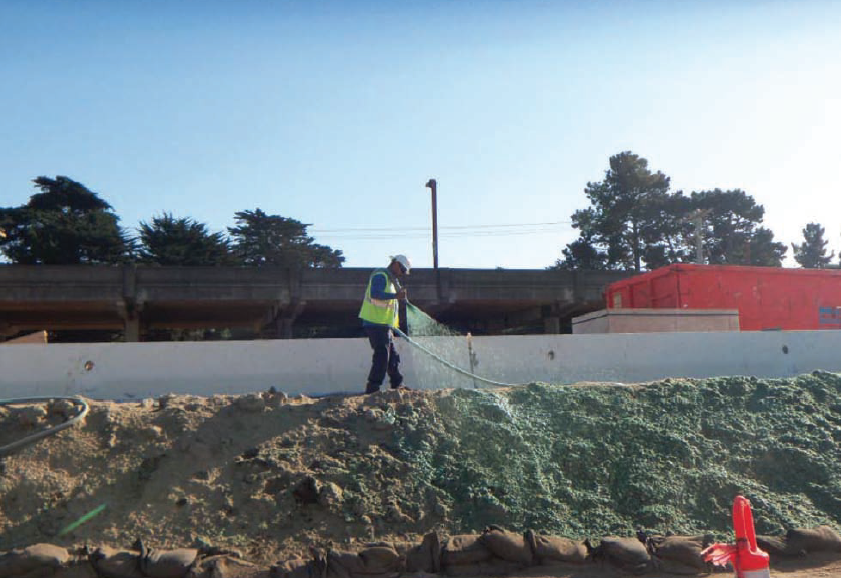
Hydraulic mulch is a mixture of wood mulch and water, with or without combinations of stabilizing emulsion, recycled paper, and/or other organic fibers. This slurry is applied to disturbed soil areas using hydro-mulching equipment to temporarily stabilize the soil and reduce erosion caused by wind and water. Common types of hydraulic mulches include organic fiber mulch and hydraulic matrix (mulches with binders added, products that are all inclusive and cover several application specifications). These products should be specified by the qualified SWPPP developer and/or landscape architect.
GUIDELINES
- Roughen the soil prior to application - refer to Soil Roughening section.
- All mulch products should be applied during a dry period for all hydraulic products.
- To be effective, hydraulic matrices require 24 hours to dry before rainfall occurs.
- Avoid mulch over-spray onto roads, sidewalks, drainage channels, and existing vegetation.
- Follow project specifications for application. Rates vary depending on slope, material type, and soils.
MAINTENANCE
Inspect BMPs prior to forecasted rain, daily during extended rain events, after rain events, weekly during the rainy season, and at two-week intervals during the non-rainy season. Maintain an unbroken, temporary mulched ground cover throughout the period of construction when the soils are not being reworked.
examples of bonded fiber matrix use
DESCRIPTION
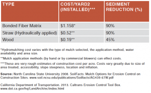
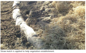
Straw mulch consists of placing a uniform layer of straw and incorporating it into the soil with a studded roller or anchoring it with a tackifier. Straw mulch is used as a temporary surface cover for soil stabilization on sites until soils can be prepared for re-vegetation.
GUIDELINES
Straw should be derived from certified weed-free wheat, rice, or barley.
Straw mulch should be distributed evenly on the soil surface. Manufacturer-suggested application rates should be followed so that mulch covers the soil in a uniform layer, without any visible bare spots.
Straw mulch may be spread with a straw blower or by hand. Be sure that air born dust is kept to a minimum. California regulations require that all straw blowing equipment meet air quality standards that diminish dust issues during application. Manual application is time- and labor-intensive.
Typical application is 4,000 lbs per acre. If applied with seed, the seed should be applied hydraulically with a 500 lb per acre trace material (paper or combination mulch), straw added, then the addition of binding material at a minimum of 250 lbs per acre or as specified.
MAINTENANCE AND INSPECTION
Inspect straw mulch prior to and after rain events. Repair any damaged areas and re-mulch exposed areas of soil.
cost estimate & efficacy
example of straw mulch use
DESCRIPTION
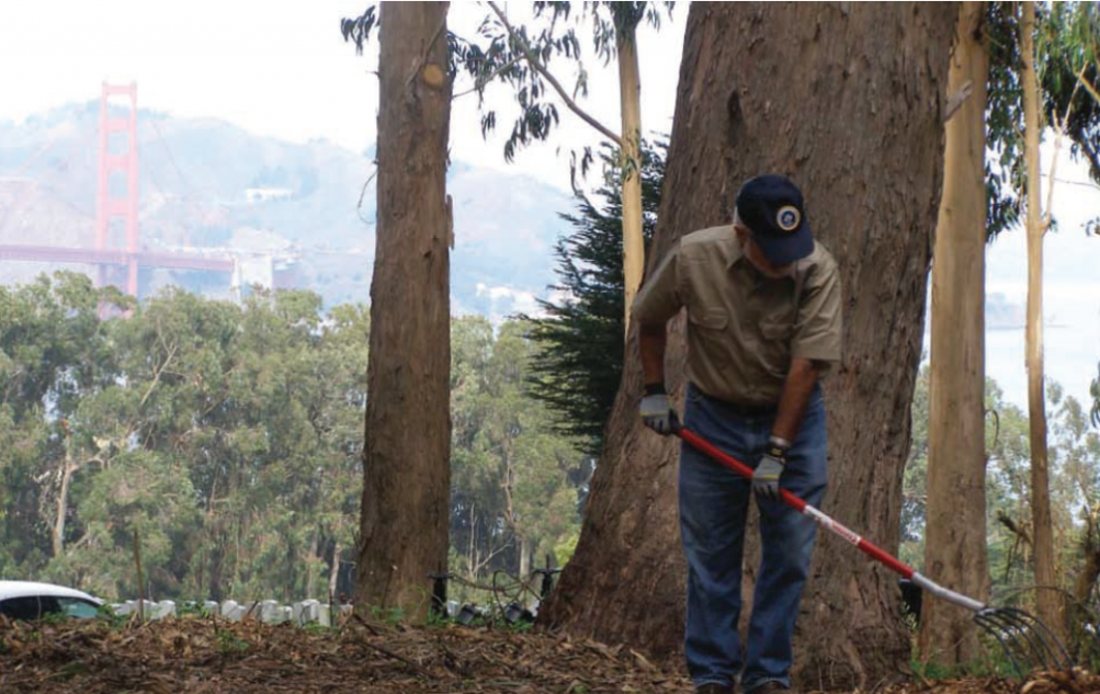
This BMP consists of applying a mixture of shredded wood mulch, bark, or compost to bare soil to reduce runoff, increase infiltration, and reduce erosion due to rainfall impact. Wood mulch may provide temporary or permanent ground cover for landscaping projects.
GUIDELINES
- Select wood mulch products appropriate for the application and site conditions.
- Application preparation involves removal of existing vegetation, filling and compaction of holes or voids, and scarifying the embankment. Depending upon the product, wood mulch should be placed at a depth of two to three inches.
Inspection and maintenance
- Monitor to assure the mulch lasts an adequate time to achieve erosion control objectives.
- Inspect areas before and after rains events.
- Repair any damaged areas by adding more wood mulch.
example of wood mulch application
DESCRIPTION
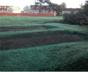
Hydroseeding consists of applying a mixture of fiber, seed, fertilizer, and stabilizing liquid mixture with hydro mulch equipment to protect exposed soils from erosion by water and wind.
APPLICABILITY
Hydroseeding may be performed on:
- Disturbed areas requiring temporary protection until permanent stabilization is established
- Disturbed areas that will be re-disturbed following an extended period (6 to 12 months) of inactivity
- Cleared and graded areas exposed to seasonal rains or temporary irrigation
- Areas not subject to heavy wear by construction equipment or high traffic
INSTALLATION
Where appropriate, soil should be prepared (see Soil Preparation section above).
- Hydraulic seed can be applied using a multi-step or a single-step process.
- In a multi-step process, hydraulic seed is applied first, followed by mulch or RECP.
- In a single-step process, hydraulic seed is applied with hydraulic mulch in a hydraulic matrix. When the one step process is used to apply the mixture of fiber, seed, etc., the seed rate should be increased to compensate for all seeds not having direct contact with the soil, or as specified by the landscape architect.
- All hydraulically seeded areas should have mulch, or an alternate erosion control cover, to keep seeds in place and moderate soil moisture/temperature until the seeds germinate and grow.
MAINTENANCE AND INSPECTION
Regularly inspect the area to ensure seed germination and vegetation establishment. Where seeds fail to germinate, the area must be re-seeded, fertilized, and mulched within the planting season, using no less than half the original application rates. Physical inspections should be performed following rain events to observe gully and displaced mulch.
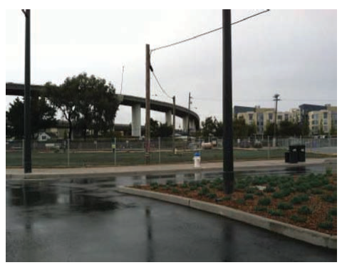
appropriate location for hydroseed
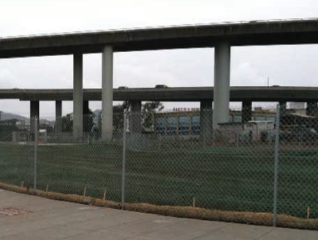
do not apply hydroseeding to high traffic areas
DESCRIPTION
Soil binders are stabilizing emulsions applied directly to the surface of disturbed soil areas or used as the stabilizer in hydraulic mulch, hydroseeding, and/or on straw mulch. Soil binders applied directly to the surface temporarily reduce erosion caused by water and wind by penetrating the top soil and binding the soil particles together.
GUIDELINES
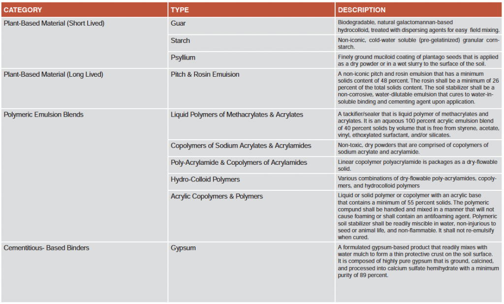
Soil binders can be effective for periods of three months or longer, depending on the requirement of the specifications. Soil binders are categorized as: short-lived plant based materials, long-lived plant based materials, polymeric emulsion blends (acrylic polymers), and cementitious-based binders.
The less durable stabilizing emulsions are called tackifiers. Short lived plant based materials, highly diluted polymeric emulsions and cementitious binders are tackifiers. They are applied directly to the soil surface or are used as the stabilizing emulsion in hydraulic and straw mulches for disturbed soil areas that require short term stabilization.
The more durable stabilizing emulsions are heavy duty soil binders. Heavy duty soil binders are applied directly to the soil surface or used as the stabilizing emulsion in hydraulic and straw mulches for disturbed soil areas that require long term stabilization. Long lived plant based materials, less diluted polymeric emulsions and cementitious binders are considered heavy duty soil binders. Soil binders are also used to stabilize temporary roads during construction. Use only those binders specified in the plans, for each application.
INSTALLATION
After selecting an appropriate soil binder, the untreated soil surface must be prepared before applying the soil binder. The untreated soil surface must contain sufficient moisture to assist the agent in achieving uniform distribution. In general, the following steps should be followed:
- Follow manufacturer’s written recommendations for application rates, pre-wetting of application area, and cleaning of equipment after use.
- Prior to application, roughen embankment and fill areas.
- Consider the drying time for the selected soil binder and apply with sufficient time before anticipated rainfall. Soil binders should not be applied during or immediately before rainfall.
- Avoid over spray onto roads, sidewalks, drainage channels, sound walls, existing vegetation, etc.
- Soil binders should not be applied to frozen soil, areas with standing water, under freezing or rainy conditions, or when the temperature is below 40°F during the curing period.
- More than one treatment is often necessary, although the second treatment may be diluted or have a lower application rate.
- Generally, soil binders require a minimum curing time of 24 hours before they are fully effective. Refer to manufacturer’s instructions for specific cure time.
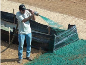
Examples of hydrAUlic mulch with Soil Binders
application of hydrAUlic mulch
MAINTENANCE AND INSPECTION
Inspect BMPs prior to forecasted and rain, daily during extended rain events, after rain events, weekly during the rainy season, and at two-week intervals during the non-rainy season. Repair eroded areas and reapply BMP as soon as possible. Minimize damage to stabilized areas while making repairs. The binder will be reapplied as needed to maintain effectiveness.
CATEGORIES OF SOIL BINDERS
DESCRIPTION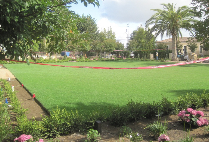
Sodding is a permanent erosion control practice and involves laying a continuous cover of grass sod on exposed soils. Sodding can stabilize disturbed areas and reduce the velocity of stormwater runoff. This BMP can provide immediate vegetative cover for critical areas and stabilize areas that cannot be readily vegetated by seed. It also can stabilize channels or swales that convey concentrated flows and can reduce flow velocities.
INSTALLATION
- In the area to be sodded, clear all trash, debris, roots, branches, stones, and clods larger than 2 inches in diameter.
- If a soil test determines the need, prepare the soil and add lime and fertilizer.
- Lay strips of sod:
- Beginning at the lowest area to be sodded.
- Perpendicular to the direction of water flow, and stagger it in a brick-like pattern.
- On slopes steeper than 30%, staple the corners and middle of each strip firmly. Place jute or plastic netting over the sod to protect against washout during establishment.
- Roll the sodded area and irrigate.
- Ensure that sod is harvested, delivered, and installed within a period of 36 hours. If it is not transplanted within this period, inspect and approve the sod before its installation.
MAINTENANCE AND INSPECTION
When mowing, do not remove more than one-third of the shoot. Maintain a grass height between 2 and 3 inches. After the first growing season, determine if additional fertilization or liming is needed. Permanent, fine turf areas require yearly maintenance fertilization. If the grass is unhealthy, the cause shall be determined and appropriate action taken to re-establish a healthy ground cover.
DESCRIPTION
Diversion structures are structures that intercept, divert, and convey surface runoff around or through the project site in a non-erosive manner.
GUIDELINES
Dikes and drainage swales are suitable for diversion use, individually or together. When properly placed and maintained, dikes used as temporary diversions can control the velocity and direction of stormwater runoff. Used by themselves, they do not have any sediment removal capability. They must be used with an appropriate sediment-trapping device at the outfall of the diversion channel. It may be necessary to use other erosion and sediment control measures such as check dams, plastic sheeting, or blankets to prevent scour and erosion in these swales, dikes, and ditches. In some cases, the swale may need to be constructed of concrete or rock. Diversion structures may be used:
- To convey surface runoff down sloping land
- Along paved surfaces to intercept runoff
- Along the top of slopes to divert surface flow from slopes
- To divert and direct runoff towards stabilized drainage systems
- Below steep grades where runoff begins to concentrate
example of earth dike/drainage swale and lined ditch
INSTALLATION
- A combination dike and swale is easily constructed by a single pass of a bulldozer or grader, and compacted by a second pass of the tracks or wheels over the ridge.
- Diversion structures should be installed when a site is graded initially. They must remain in place until post construction BMPs are installed and slopes are stabilized.
- Temporary diversion dikes should not adversely impact adjacent properties and should not be used in areas with slopes steeper than 10%.
- Provide stabilized outlets.
- Divert sediment-laden runoff into sediment traps.
MAINTENANCE AND INSPECTION
Check channels, embankments, and ditch beds. If erosion, washout, and/or accumulation of sediment and debris are found:
- Remove the sediment accumulation and debris.
- Repair/replace lost riprap, linings, or soil stabilization, as needed.
DESCRIPTION
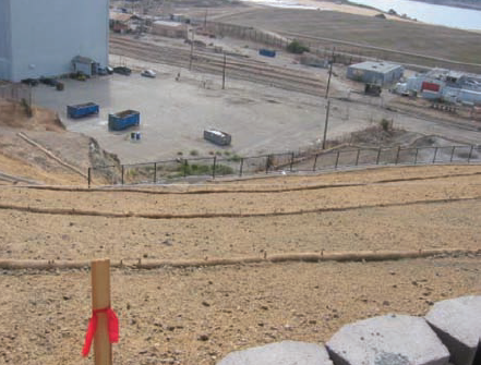
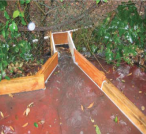
Slope drains convey water down a slope into a stabilized water trapping device or area. Slope drains are used with lined ditches atop a fill bank to convey surface flow away from incline areas and to protect exposed slopes.
GUIDELINES
- Install slope drains perpendicular to the slope contour.
- Drain pipes must be securely anchored to the slope and must be adequately sized to carry the capacity of the design storm and associated forces.
- Compact the soil around and under the slope drain inlet, outlet, and along the length of the pipe. Protect the pipe inlet with filter fabric. Use flared end sections for inlets and discharges for pipes 12 inches in diameter and larger.
- Protect the discharge outlet with riprap or other velocity dissipation devices. For high velocity discharge, integrate concrete into the riprap.
MAINTENANCE AND INSPECTION
Inspect prior to and after each rain event and twice monthly until the upstream drainage area is stabilized.
Inspect outlets for erosion and downstream scour. In the event of scour, reduce the flows into the channel unless other preventative measures can be implemented.
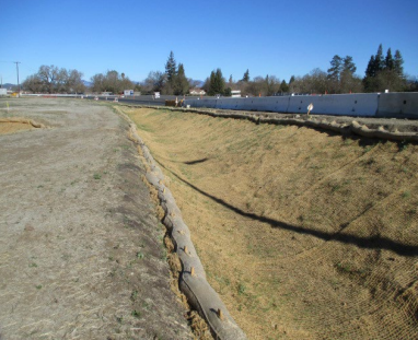
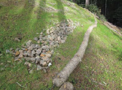
temporary diversion structure built upstream from a steep slope, preventing runoff from causing hillside erosion
DESCRIPTION
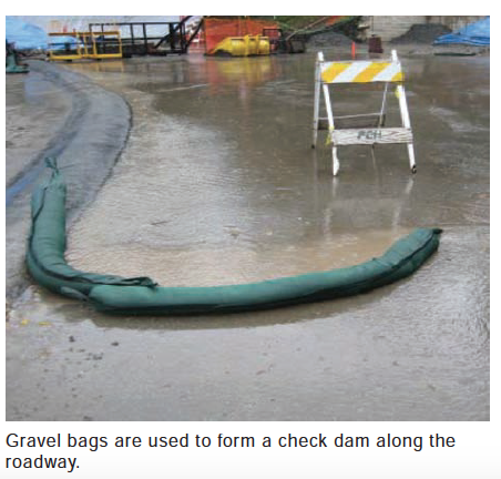
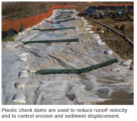
Check dams are small structures placed across a natural or man-made drainage channel to reduce scour and erosion by reducing flow velocity and encouraging sediment deposition. They are typically constructed of gravel rock bags, rip rap, or fencing - depending on site conditions and material availability.
GUIDELINES
Check dams are generally used in:
- Small open channels;
Steep channels where runoff velocities exceed five feet per second; - Ditches or channels where grass linings are being established; or
- Temporary ditches where short term service does not warrant establishment of erosion resistant linings.
INSTALLATION
- Install check dams approximately 20 feet from the intake structure and at regular intervals along the channel. Space dams closer together where there is a high potential of erosion (steep grades and/or high flows).
- Embed structure sufficiently in sides and bottom of channel to prevent undercutting.
- The dams should be placed at a height and distance allowing small pools to form behind them but also allowing high velocity runoff (typically a two year storm or larger) to safely flow over them without an increase in upstream flooding or damage to the dam.
- Stabilize channel immediately downstream of check dams to prevent erosion at the toe of the structure.
- If using a prefabricated check dam, follow manufacturer’s recommendations and installation instructions.
MAINTENANCE AND INSPECTION
Perform maintenance as required. Inspect following rainfall events and at least daily during prolonged rainfall. Maintain to provide an adequate sediment holding capacity. Remove debris daily and remove sediment when it accumulates to 1/3 of the dam height.
examples of check dams
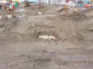
DESCRIPTION
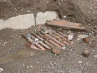
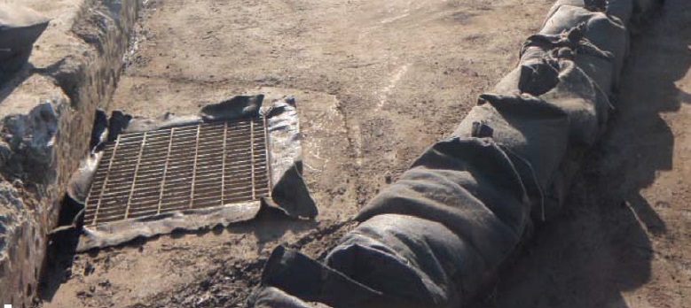
Drain inlet and catch basin protection reduces sediment entering the storm drain system carried by runoff from a construction site. These systems allow sediment to settle out of water or filters sediment from the water before it enters the drain inlet. All inlets and basins connected to the storm drain system must be protected - the last line of defense for water quality prior to entering the drainage system.
There are several types of inlet and catch basin protection measures:
- Excavation around the perimeter: Excavating an area around an inlet creates a settling pool that removes sediments as water is released slowly into the inlet through small holes protected by gravel and filter fabric.
- Reusable barriers around drain entrances: Erecting a barrier made of plastic filtration fencing creates a shield against sediment while allowing water to flow into the drain. This barrier slows runoff while catching soil and other debris at the drain inlet.
GUIDELINES
unprotected inlets
MAINTENANCE AND INSPECTION
Check all temporary control measures before and after each storm event. During extended storm events, inspect at least once every 24 hours.
- Remove accumulated sediment from the area around the drop inlet and catch basin when the capacity is reduced by half.
- Remove additional debris from the shallow pools periodically. The weep holes in excavated areas around inlets can become clogged, preventing water from draining out of the pools.
- Clear sediment build around barrier.
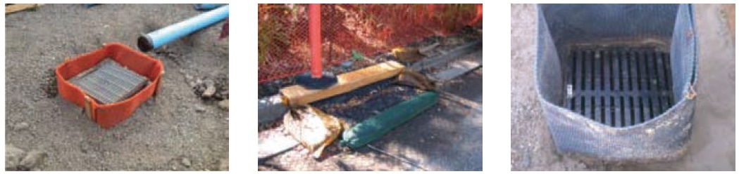
examples of properly protected inlets
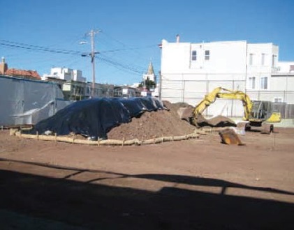
description
Fiber rolls can be used:
- Around temporary stockpiles
- As perimeter control
- At the top of slopes to intercept sheet flow from flatter areas
- At the bottom of the slopes
- Parallel to the contours of the slope
- To shorten slope length of exposed and erodible slopes along face or at-grade breaks
- Perpendicular to the flow lines in ditches and swales
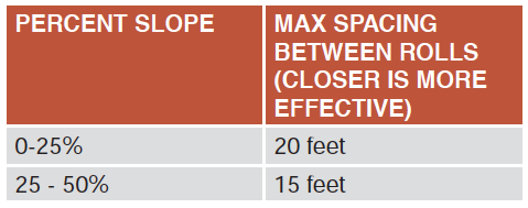
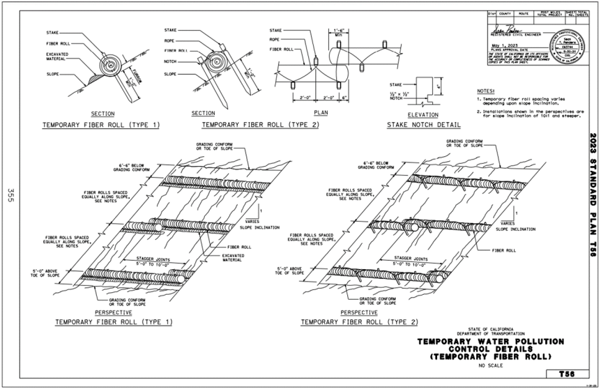
GUIDELINES
If more than one fiber roll is placed in a row, the rolls should be overlapped by at least one foot.
The diameter of the stake should be approximately 1” for ease of driving through the roll. Refer to manufacturers’ installation instructions for proper installation.
MAINTENANCE AND INSPECTION
The maintenance requirements of fiber rolls are minimal. Regular inspection is recommended to ensure that the rolls remain firmly anchored in place and are not excessively crushed/damaged by equipment traffic.
- Inspect fiber rolls before and after rain events, and at least daily during prolonged rainfall.
- Repair or replace split, torn, unraveled, or slumping fiber rolls. Fiber rolls typically are left in place on slopes after construction is complete, as part of site stabilization. If they are removed, collect and dispose of the accumulated sediment.
- After removal, fill and compact holes, trenches, depressions, and any other ground disturbance to blend with the surrounding landscape.
LIMITATIONS
- Difficult to move once saturated. Some saturated fiber rolls may require a crane or other machinery to remove from site.
- If not properly staked and trenched in, fiber rolls can be displaced by high flows.
- Fiber rolls have a very limited sediment capture zone.
- Fiber rolls should not be used on slopes subject to creep, slumping, or landslide. Use RECP with stronger soil stabilizing properties.
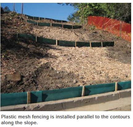
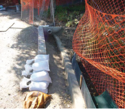
ALTERNATIVES
Polyethylene sediment-filtration fencing can be used as a substitute for the traditional fiber roll. This reusable and recyclable product is used for slope protection and stabilization. It slows the velocity, spreads the flow of runoff, and removes pollutants and sediment from runoff. These products are easy to install, lightweight, and highly resistant to vehicle and foot traffic.
examples of properly installed fiber rolls
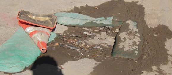
do not install on top of obstructions
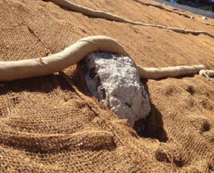
Remove or bypass obstructions only.
DESCRIPTION
A silt fence is a temporary linear barrier that captures sediment by retaining runoff, allowing the sediment to settle out. The fences are typically made of a non-woven geotextile and come in standard or heavy-duty strength.
Silt fences can be used:
- Along the contour of a slope
- Below the toe or down slope of exposed or erodible slopes
- Below other cleared areas
- In areas where sheet flow occurs
GUIDELINES
The fence should be installed on a level contour. The ends of the fence should be angled up stream to prevent sedimentary laden water from running around the ends.
- Excavate a 6 inch wide by 6 inch deep trench along the line of the fence. Backfill the trench with native material.
- The bottom 12 inches of fence should be securely placed into the ground.
- Stake posts a maximum of 6 feet apart, and secure posts at a minimum depth of 18 inches.
- Where additional structural support is needed, fasten a plastic or wire mesh support fence to standard strength silt fence.
MAINTENANCE AND INSPECTION
Silt fences can be maintenance intensive. Perform inspections before and after every rain event, and every 24 hours during extended rain events. Weekly inspections throughout the rainy season are recommended. Remove sediment deposits when they reach 1/3 of the fabric height. All torn or decomposed fencing should be replaced. Do not allow water or sediment depth to exceed 1.5 feet at any point. The fence should remain in place until the disturbed area is permanently stabilized.
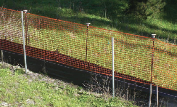
examples of properly installed silt fences
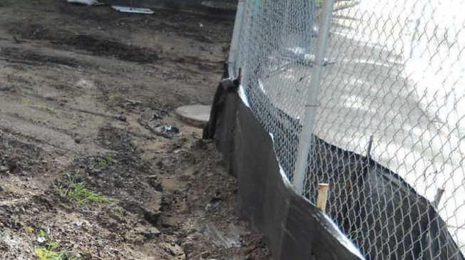
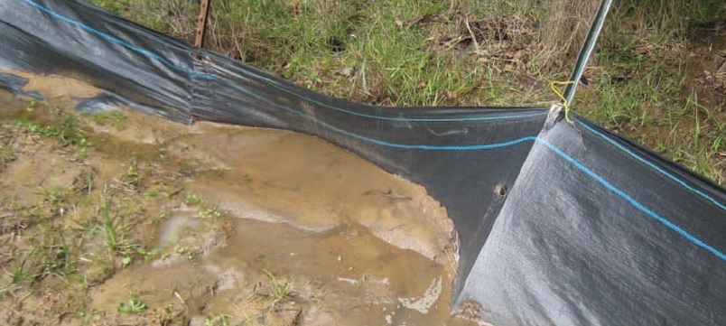
incorrect installation of silt fence
ALTERNATIVES
Temporary high density polyethylene sediment-filtration fencing can be used as a substitute for the traditional silt fence. This reusable product which is made from recycled materials, is used for slope and perimeter protection. It slows the velocity and spreads the flow of runoff while handling larger floods and pressures. The filter removes pollutants and sediment from the runoff. These products are easy to install, durable, and lightweight.
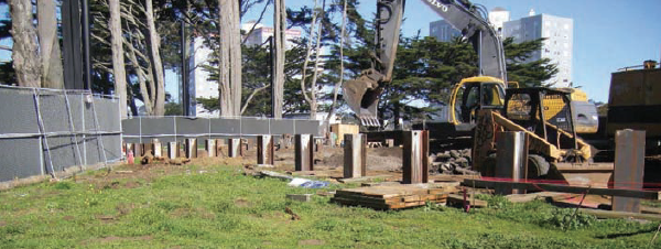
extend silt fence to the top of perimeter fencing for wind control and site security
DESCRIPTION
A gravel berm consists of a row of gravel bags installed end to end. Berms form a barrier across a slope to intercept runoff, reduce runoff velocity, and release runoff as sheet flow after providing some sediment removal.
Berms are used as linear sediment control measures. Suitable locations include:
- At the top, toe, face, and grade break of slopes
- Along a roadway to keep sediment off paved areas
- At the perimeter of sites
- As sediment traps at drainage outlets
INSTALLATION
A gravel bag berm intercepts and slows sheet flow runoff, causing temporary ponding. This provides a stagnant area for sediment to settle. The gravel is porous, which allows the ponded runoff to flow slowly through the bags, releasing the runoff as sheet flow.
- Locate gravel bag berms on level contours
- Locate bags at the following intervals when placed along slopes:
- 4:1 or flatter slope: place bags at 20 ft intervals
- 4:1 to 2:1 slope: place bags at 15 ft intervals
- 2:1 or greater: place bags at maximum of 10 ft intervals
MAINTENANCE AND INSPECTION
This BMP is labor- and maintenance-intensive. Inspect gravel bags before and after rain events, and weekly during the rainy season.
Repair and replace broken or ripped bags, and remove accumulated sediment when it reaches 1/3 the height of the bag.
examples of properly installed gravel berms
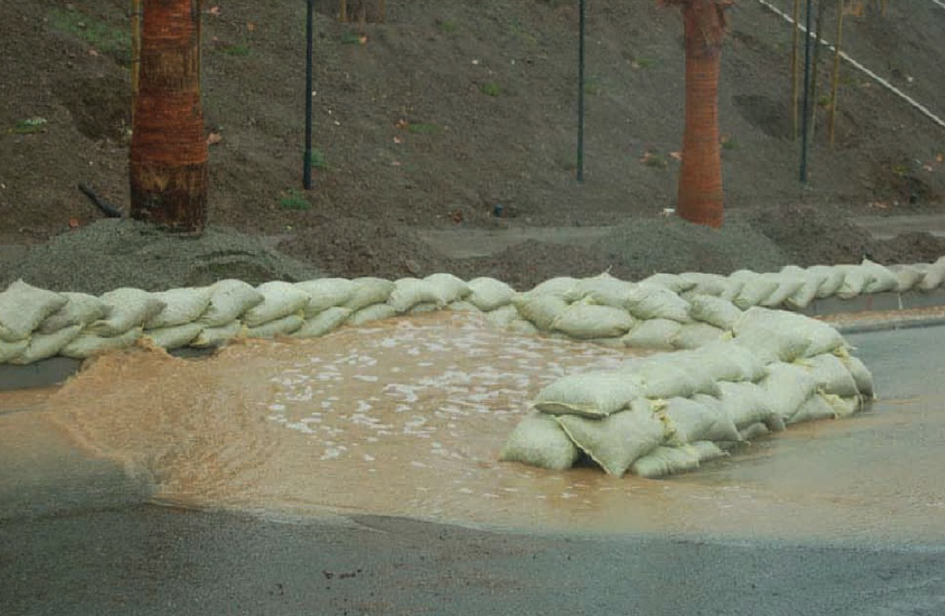
failed gravel berm
description
This is a temporary settling area formed by:
- Shallow excavation
- Perimeter construction of an earthen embankment
- Embankment constructed across a waterway or low drainage area
It includes a controlled release structure like a sump pump or overflow structure.
The sediment trap is used as a pretreatment measure for entry of the runoff into the storm drain system or natural waterway. This BMP allows sediment to settle out of runoff prior to the discharge of the water into the local storm drainage system or natural waterway.
GUIDELINES
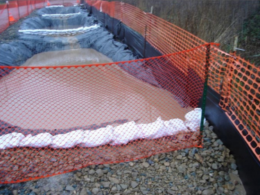
The trap should be excavated where breech of the perimeter would not pose a risk to life or property. Access should be provided for maintenance including sediment removal.
The length of the trap should be more than three times the width. Traps with levees greater than five feet in height should be designed by a professional civil engineer. The trap inlet should be located as far as possible from the outlet structure in order to allow maximum sediment settlement. Traps may require protective fencing to ensure safety.
MAINTENANCE AND INSPECTION
Traps should be inspected before and after every rain event, weekly during the rainy season, and at 24-hour intervals during extended storms. Check inlet and outlet structures and spillways for signs of erosion, damage or obstructions. Examine trap banks for seepage and structural soundness. Remove accumulated sediment when the storage trap is 1/3 full.
To assist with vector control, vegetation should be removed from the basin frequently.
- Sediment accumulates in trap and settles out of runoff
- Overflow structure discharges clean water to storm drains
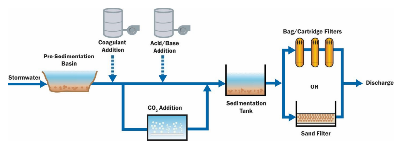
DESCRIPTION
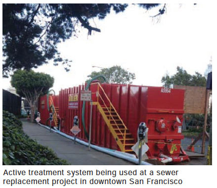
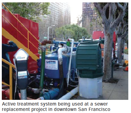
An active treatment system uses a coagulant for the treatment of water with a sedimentation basin for facilitating turbidity reduction and is required when:
- Traditional erosion and sediment applications are not effective
- When zero discharge is a condition of construction for a project
One key distinction between this BMP and others is that it is “Active,” requiring a power source. These systems require detailed analysis of site conditions and hydrology associated with the site’s stormwater management. The system is designed by the project engineer and managed/maintained by certified ATS personnel.
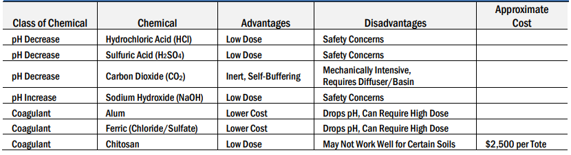
The primary treatment process with an ATS is the employment of chemical coagulation, chemical flocculation, or electrocoagulation in order to reduce turbidity caused by suspended sediments. Any chemical materials specified in the ATS must be approved by the California State Water Resources Control Board (SWRCB). These systems usually require review and approval by the Regional Water Quality Control Board (Region 3).
APPLICABILITY
Use this BMP, per the design criteria and requirements described in the SWRCB Construction General Permit (CGP), when:
- Discharging to turbidity sensitive waters, and turbidity reduction by other BMPs is insufficient
- Where site constraints limit the ability to construct a properly sized sediment trap
- Where use is required by the CGP
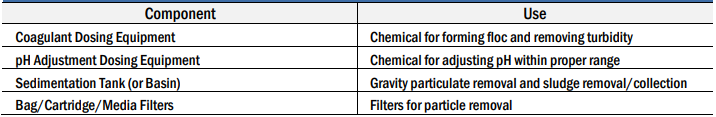
GUIDELINES
Chemically treated stormwater discharged from construction sites should:
- Be designed and approved by a Certified Professional In Erosion and Sediment Control (CPESC), a Certified Professional in Stormwater Quality (CPSWQ), or a California registered civil engineer.
- Meet residual chemical and toxicity requirements as defined in the CGP.
- Include a filtration step between the coagulant treatment train and the effluent discharge.
- Be done in accordance with all local, state, and federal laws and regulations.
- Should be equipped with instrumentation that automatically measures and records effluent water quality data and flow rate.
- Comply with all provisions and prohibitions in the CGP.
- The project shall have a site-specific Operation and Maintenance (O&M) manual covering the procedures required to install, operate, and maintain the ATS.
- Operators shall have training specific to using an ATS and liquid coagulants for storm water discharges.
- Any discharger who deploys an ATS on their site shall conduct the daily visual monitoring and record findings in the project data log.
MAINTENANCE AND INSPECTION
Daily on-site visual monitoring of the ATS operation and performance shall be done by a qualified person as required. The name and phone number of the qualified person assigned the responsibility of operation and monitoring of the system, and documentation of the qualified person’s training as required by the statewide General Construction Stormwater Permit will need to be provided on site.
ATS require continuous monitoring when operating. Special attention needs to be given to ATS whenever they are being started up for the first time, restarted after an extended down time, and after maintenance/repair work has been done on the system.